
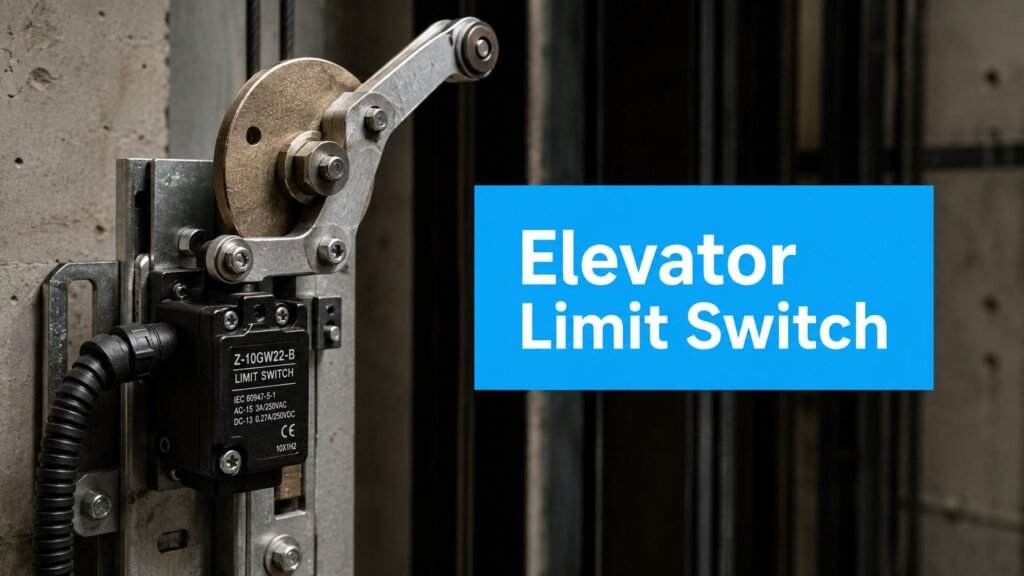
The elevator begins creeping past the terminal floor. The doors stay closed, and the controller reports a limit fault. From the lobby, the facility manager sees one failure. In the hoistway, the cause could be a slow-down switch, a normal terminal stop switch, a final limit circuit, a misaligned cam, or a damaged actuator. The planning question is therefore specific: which layer of the stopping system operated incorrectly?
An elevator mechanical limit switch does not have one universal job. Separate switches may control slow-down, normal terminal stopping, and final overtravel protection. Replacing a switch before identifying its function can leave the fault untouched. Incorrect adjustment can also turn a leveling problem into a safety shutdown.
These switches convert actual machine movement into a hard-wired electrical change. Industrial switch families commonly reference EN 50041 and EN 50047 for dimensions, actuator operating points, terminal markings, and minimum ingress protection requirements. Elevator-oriented models may also follow IEC 60947-5-1 / EN 60947-5-1, with model-dependent ratings reaching 10A and voltages up to 500VAC or 600VAC, as shown in industrial limit-switch documentation.
The useful starting point is the switch's role, not its appearance. A technician must trace the circuit, inspect the actuator and cam contact, then confirm whether the car is stopping at the intended position.
What an Elevator Mechanical Limit Switch Does
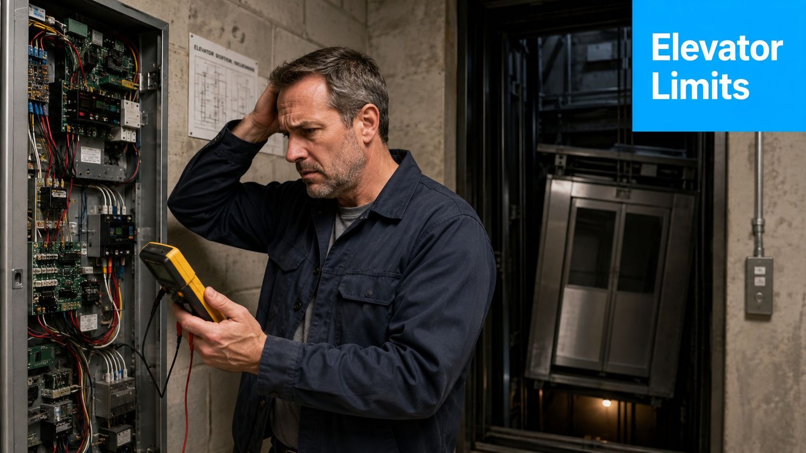
A facility manager sees the car approach the top floor too quickly. It does not hit the landing, but it creeps, corrects itself, and sometimes refuses to level. On another trip, the car stops short and the controller locks it out. From the lobby, both events look like a failed limit switch. In the hoistway, they may involve a slow-down switch, a normal terminal stop switch, a final limit circuit, a misaligned cam, or a wiring fault.
A mechanical limit switch is a physically actuated electromechanical switch. A cam, vane, dog, or lever mounted on the car, counterweight, or hoistway contacts its actuator at a defined position. The actuator may be a roller lever, plunger, or flexible rod. As the moving hardware pushes it, internal contacts change state and send a signal to the elevator controller.
Why physical contact matters
A proximity sensor detects an electronic field across a set distance. A mechanical switch requires something to physically move the actuator. Alignment, spring return, lever condition, cam position, and mounting security therefore affect both mechanical operation and electrical reliability.
Terminal switches help manage the car's approach to the ends of travel in geared traction and hydraulic elevators. A slow-down device commands reduced speed. A normal stop device commands the intended terminal stop. A final limit interrupts the safety circuit if the car travels beyond that normal stopping layer. These functions are separate, so the switches are not interchangeable.
Practical rule: A “limit switch problem” identifies a symptom category, not a replacement part.
Generic online advice often says to replace the top or bottom limit. That instruction skips the diagnosis. The complaint may involve leveling, normal stopping, or final overtravel protection. The actuator may be operating correctly while the cam, wiring, controller input, or brake circuit causes the fault.
For planning discussions, ask which stopping layer is involved and what the car did at the terminal floor. Then have the technician trace the relevant circuit and inspect the related hardware. For broader context, review elevator control-system components and how they integrate.
Inside the Switch and How It Trips
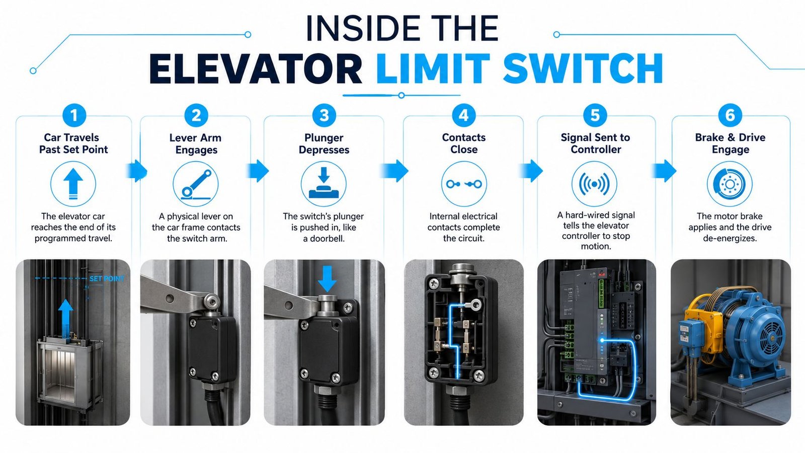
An apprentice can understand the operating sequence with a doorbell. You press the button, the internal contacts change position, current follows a circuit, and the chime responds. An elevator mechanical limit switch does the same basic conversion, but a moving car or cam supplies the pressure instead of a person's finger.
The action from actuator to controller
The actuator receives the contact. A roller lever, straight lever, plunger, or wobble-style actuator sits outside the housing. The cam or vane pushes it as the car passes the set point.
The return spring stores force. As the actuator moves, the spring prepares to return it after the cam clears. If the spring is weak, contaminated, or damaged, the switch may not restore its expected state.
The internal mechanism pivots. The actuator moves a contact arm inside the body. That arm transfers the mechanical movement to the electrical contact assembly.
Snap-action contacts change state. The contacts open, close, or transfer between circuits. The snap action is important because it limits slow contact movement and reduces chatter while the cam engages.
The terminals carry the signal. Terminal markings on the switch connect the contact arrangement to the controller or safety circuit. The controller then interprets the state change as a command or protective event.
Housing and adjustment are part of the design
Switch bodies may be compact plastic, die-cast metal, or oil-tight enclosures. The correct housing depends on exposure to moisture, dust, oil, vibration, and physical impact. The outer body protects the contact mechanism, but the actuator style determines whether the switch can survive the actual cam movement.
Quality devices also have defined pretravel, operating point, over-travel, and reset position. Technical elevator documentation describes actuation deviation around ±1 mm and repeat positioning accuracy at or below 0.5 mm in some switch families, as summarized in the IS 14665 elevator safety standard reference. Those figures aren't permission for an owner to adjust a switch by eye. They show why a small change in mounting or cam geometry can affect the control sequence.
A field technician may replace the complete switch, or in some designs replace a compatible contact block. That decision depends on the manufacturer's construction, the circuit's safety requirements, and the condition of the actuator and housing. The same actuator-and-cam principle appears at the slow-down, normal stop, and final-limit positions, but the consequence of each trip is different.
For a visual walk-through of the mechanism and stopping sequence, use this elevator limit switch explainer video.
Slow-Down, Normal Stop, and Final Limit Explained
The most important distinction is that slow-down, normal stop, and final limit switches are separate layers. They act in sequence as the car approaches a terminal landing, but they don't carry the same responsibility or produce the same kind of shutdown.
| Function | Trip Point | Reset Method | Circuit Effect | Failure Mode |
|---|---|---|---|---|
| Slow-down limit | Approaching the terminal landing | Usually restores when the cam clears | Commands the controller to reduce travel speed | Car approaches too fast or reaches the landing inconsistently |
| Normal terminal stop | Beyond the slow-down action point | May require technician reset or inspection, depending on design | Commands the normal terminal stop | Car travels too far or stops with a terminal fault |
| Final limit | Beyond the normal stopping layer at the extreme end of travel | Typically requires qualified inspection and reset | Opens the safety circuit and removes the run permission | Hard shutdown and loss of normal service until the cause is corrected |
The first layer changes speed
The slow-down limit gives the controller time to reduce the car's speed before the terminal floor. If the car passes the cam without receiving that signal, it may enter the landing zone too quickly or fail to complete the expected leveling sequence. A complaint that appears as late leveling can therefore originate with the switch, its cam, its wiring, or the speed-control logic that receives the signal.
The second layer commands the normal stop
The normal stopping limit sits farther along the travel path. It provides another stopping action if the slow-down instruction wasn't followed correctly. Treating this switch as though it were the final safety device can confuse troubleshooting because a normal terminal fault and a final-limit trip have different implications for the safety circuit and reset process.
The final layer protects against overtravel
The final limit is intended for abnormal overtravel. Code-based elevator references distinguish terminal slow-down, normal stopping, and final-limit functions, with the final limit serving as the last protective stage beyond normal landing positions. The historical development of standardized terminal protection is reflected in national rules such as India's IS 14665-3-1 to -2, formalized in 2000, as shown in the standard's published text.
For an owner, the diagnostic shortcut is useful. A recurring leveling complaint points the technician toward the normal travel sequence. A hard shutdown at the top or bottom points toward a safety-layer event. Those observations don't prove which part failed, but they prevent the team from treating every limit fault as the same repair.
Signs Your Limit Switch Is Wearing Out
The first warning usually isn't a visible broken switch. It's a changed stopping pattern. The car may slow later than usual, stop inconsistently at a terminal floor, or refuse to run after a controller reset. A final limit that trips can leave the elevator stopped at an extreme position, but the trip itself may be the system protecting the building from a deeper travel problem.
Match the symptom to the behavior
Watch for these field clues:
- Changed terminal approach: The car enters the top or bottom landing faster than it used to, suggesting a slow-down signal, cam position, or input problem.
- Inconsistent stopping: The car stops correctly on one trip and runs long or short on another. Intermittent contacts, vibration, loose mounting, or marginal actuator travel deserve attention.
- Abrupt shutdowns: A sudden stop or repeated reset call may involve a final limit, but door circuits, brake operation, and other safety devices can create similar lockouts.
- No-run condition: A controller may refuse operation because a normally closed safety path is open. The open path might be the switch, its terminals, the wiring, or another device in series.
- Mechanical noise: Buzzing, clicking, or chattering near the switch can indicate unstable contact movement, a damaged roller, or an actuator that isn't moving cleanly.
A technician should inspect for a bent lever, cracked roller, loose mounting screws, corroded terminals, moisture, and a cam that strikes the actuator off-center. An increase in the distance the car travels before the contact changes state is especially useful. It can point to actuator wear, mechanical drift, or a shifted cam rather than an electrical failure inside the switch.
| Observed Sign | Possible Limit-Switch Issue | Related Area to Check |
|---|---|---|
| Late terminal slow-down | Slow-down switch moved or actuator worn | Cam position, controller input, drive response |
| Hard top or bottom shutdown | Final limit operated or remains open | Final-limit mounting, safety circuit, overtravel condition |
| Fault appears intermittently | Contact wear, vibration, or loose terminal | Wiring, connectors, controller input |
| Car won't run after reset | Open safety contact or failed return | Switch spring, door circuit, brake circuit, inspection circuit |
| Stopping varies with conditions | Marginal mechanical engagement | Temperature effects, contamination, alignment, linkage |
Record the direction of travel, floor, speed, frequency, and whether the car stopped early, late, or hard. Don't assume the switch is at fault just because the controller names a limit input. The event pattern helps separate the switch from the actuator, wiring, door system, leveling equipment, or brake.
How Technicians Test and Troubleshoot in the Field
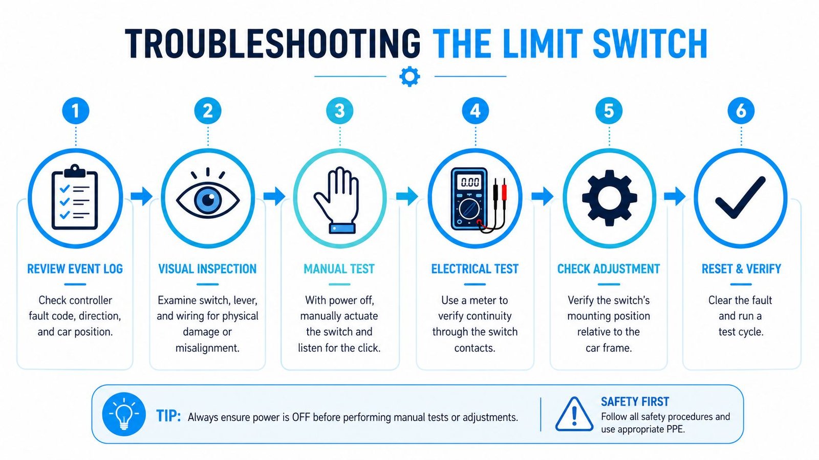
A car stops late at a terminal, and the controller reports a limit input. That record starts the diagnosis, but it does not identify the failed part. The technician compares the fault, direction of travel, car position, and stopping behavior before anyone orders a replacement.
A safe diagnostic sequence
The elevator is removed from normal service under the site's approved lockout and safety procedure. The technician examines the device without defeating the safety circuit or entering the hoistway unnecessarily.
- Review the fault history. Compare the controller input and event timing with the reported direction and floor.
- Inspect the hardware. Check the switch body, mounting, actuator, roller, cam contact, terminals, and signs of heat or moisture.
- Check mechanical movement. With power isolated as required, confirm that the actuator moves freely, changes state positively, and returns fully.
- Verify continuity. With the circuit de-energized and isolated, a multimeter can check normally open and normally closed contacts.
- Measure actuation travel. During controlled inspection movement, compare the contact-change point with the approved terminal position and manufacturer settings.
- Trace beyond the switch. If the switch passes, inspect the cam, linkage, wiring, connectors, controller input, drive response, brake circuit, and related stopping logic.
The switch should have positive overtravel after the contact changes, without the lever bottoming against the body. Sliding it randomly along its mounting slots is not a repair. That adjustment can conceal a shifted cam, leveling problem, or controller fault, while reducing the intended separation between the slow-down, normal-stop, and final-limit layers.
What justifies replacement
Replacement is reasonable when contacts are pitted, the actuator is loose, the roller is damaged, the body is cracked, or electrical readings remain unstable. A clean continuity reading proves only that the contacts can conduct at that moment. The switch must change state at the correct mechanical position and return properly afterward.
A final-limit test or safety-circuit adjustment requires qualified elevator personnel. The service record should identify the fault, adjustment, part condition, test method, actuation position, and technician sign-off. Building staff can help by recording exactly where and how the car stopped, then keeping passengers away from an elevator with a terminal or safety fault. Review the elevator testing service information to understand the controlled verification required before return to service.
Choosing the Right Replacement Switch
A replacement switch should match the function, circuit, actuator, mounting, and environment. Appearance is a poor selection method. Two switches may have similar housings but different contact arrangements, operating points, force requirements, or safety characteristics.
Start by identifying the failed layer. Record whether the device is a slow-down switch, normal terminal stop, or final limit. Photograph the label and wiring before removal, then capture the manufacturer, part number, hoistway position, contact arrangement, and actuator orientation. The replacement must reproduce the original electrical sequence, not merely fit the mounting plate.
Electrical decisions
Check the actual circuit requirements rather than relying on a controller's nominal voltage. Confirm:
- Contact form: Verify normally open, normally closed, or changeover contacts and the required state when the switch is at rest.
- Switching load: Consider current, voltage, inductive load, inrush, and whether the circuit drives a relay, input, brake control, or safety chain.
- Safety function: Confirm whether the design requires positive opening or another safety-related contact behavior.
- Terminal arrangement: Match terminal markings, wire entry, conductor size, and the existing enclosure method.
Industrial documentation shows why ratings must be read from the model data. Elevator-oriented mechanical switches are commonly specified to 10A, with voltage ratings reaching 500VAC or 600VAC depending on model, under IEC and EN safety-switch documentation. That doesn't mean every replacement can carry those values, or that a higher rating automatically makes it suitable.
Mechanical and environmental decisions
The actuator has to meet the cam's geometry. Compare roller diameter and material, lever length, plunger style, operating force, pretravel, overtravel, reset position, and mounting-hole pattern. A switch with the correct electrical contacts can still fail if its roller meets the cam too early, too late, or at an angle.
| Decision Group | What to Verify | Why It Matters |
|---|---|---|
| Function | Slow-down, normal stop, or final limit | Determines the required circuit behavior and test method |
| Contacts | NO, NC, changeover, and safety contact action | Preserves the controller's intended logic |
| Actuator | Roller, lever, plunger, force, travel, and reset | Ensures reliable physical engagement |
| Mounting | Hole pattern, orientation, and adjustment range | Keeps the original trip point |
| Enclosure | Plastic, metal, oil-tight, and sealing needs | Protects against the hoistway environment |
| Documentation | Manufacturer approval and test record | Supports safe installation and future troubleshooting |
Match the enclosure to dust, oil, moisture, cleaning water, temperature, and vibration. Add shielding or drip protection only if it doesn't restrict the actuator. When the elevator OEM specifies an approved component, use it. For a substitute, obtain written compatibility confirmation from the controller or elevator manufacturer.
Document old and new part details, wire positions, electrical readings, actuation position, test results, and technician sign-off. Technical documentation also describes some modern safety switch families with durability ratings of up to 3 million operations or more, which illustrates the long-life design goal, not a guarantee for every model or installation. Industrial switch documentation should control the actual selection.
Maintenance, Inspections, and Code Considerations
Limit-switch maintenance belongs on the scheduled safety plan, not only after a car strands passengers. Requirements vary by jurisdiction, elevator type, equipment age, and adopted code edition. North American planning commonly references ASME A17.1 / CSA B44, while other installations use national or regional rules that distinguish terminal slow-down, normal stopping, and final-limit functions. For a practical overview, review these elevator code requirements with the authority having jurisdiction and the elevator contractor.
The owner does not need to perform the test. The owner should confirm which device was tested, what response was expected, and what evidence was recorded.
What the technician examines
During planned service, the mechanic checks mounting, actuator travel, cam engagement, terminals, enclosure condition, and contact operation. Lubrication belongs only where the manufacturer permits it. A general-purpose oil can attract contamination or interfere with the contact mechanism.
A useful record connects the mechanical action to the controller response:
- Visual condition: Record bent levers, damaged rollers, cracked bodies, corrosion, contamination, and loose fasteners.
- Mechanical action: Confirm smooth movement, spring return, proper overtravel, and square cam engagement.
- Electrical condition: Check terminals, insulation, contact continuity, and overheating with appropriate isolation.
- Functional result: Record whether the car slowed, stopped, or entered the safety state at the intended position.
- Paper trail: File controller prints, wire numbers, device identifiers, test results, adjustments, and technician sign-off.
For the planning meeting: Ask whether the contractor tested the slow-down, normal stop, and final limit as separate functions. “The limits were checked” does not identify which layer passed.
Some jurisdictions require witnessed periodic tests. An inoperative safety device may be recorded as a deficiency, not a recommendation. The adopted local code and the contractor's approved method should establish the interval and procedure. Missing drawings, unfiled wire numbers, or absent test records can delay re-inspection after the mechanical fault is corrected.
A practical owner checklist
Schedule terminal cams and switches for verification during preventive maintenance. Ask for a trend record of actuation position or drift when the equipment supports that measurement. After a final-limit trip, abnormal overtravel, water intrusion, collision, or modernization work, require documented inspection before normal service resumes.
Keep old and replacement part details, wire positions, electrical readings, actuation position, test results, and sign-off together. Technical documentation describes some modern safety switch families with durability ratings of up to 3 million operations or more. That illustrates a design goal, not a guarantee for every model or installation. The industrial switch documentation should govern the actual selection and service instructions.
IS 14665-3-1 to -2, formalized in 2000, reflects the move toward standardized terminal protection and limit-switch control logic, as described in the published Indian elevator safety standard. The hardware is simple to see, but safe operation depends on mechanical adjustment, electrical continuity, controller logic, and a verified response.
Crane Elevator Company helps building owners in Michigan and Ohio diagnose terminal faults, test elevator safety devices, correct code violations, and plan non-proprietary modernizations for all makes and models. Visit Crane Elevator Company to request a qualified assessment, second opinion, or maintenance and testing plan for elevator mechanical limit switches.