
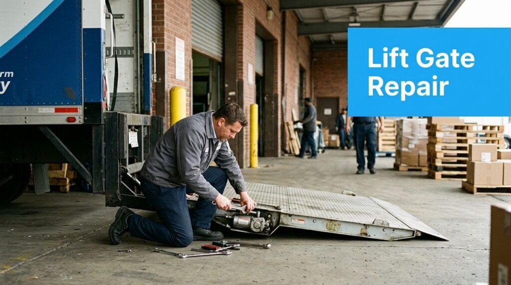
The truck is backed to the dock, the delivery is ready to move, and the lift gate only clicks when the driver presses the control. Someone suggests adding hydraulic fluid. Someone else wants to replace the pump. Both may be wrong. Many liftgate failures begin in the electrical path, then present as a hydraulic problem because the motor never receives enough power to generate usable flow.
Hydraulic lift gate repair starts with controlled diagnosis, not parts replacement. Treat the equipment as a load-bearing machine, isolate it before inspection, and separate electrical, hydraulic, mechanical, and structural symptoms before deciding who should repair it.
Why Hydraulic Lift Gates Fail and What to Expect From This Guide
A lift gate may quit at the dock for several unrelated reasons. Fleet service reporting places electrical faults first, especially failed switches and motor solenoids, followed by electric motors. Valve and coil problems come next. Pump or motor failures account for less than 5% of reported cases, according to Fleet Maintenance's liftgate repair guidance.
That sequence changes how the repair should begin. A weak battery, corroded ground, damaged cable, or failed solenoid can prevent the motor from receiving enough power. The symptoms look hydraulic: slow platform travel, movement that stops under load, or a gate that will not rise. Opening the hydraulic circuit first can waste time and add contamination.
Safety comes before diagnosis
Apply lockout/tagout before handling the gate, controls, battery connections, or hydraulic components. Park the truck on suitable ground, account for uneven surfaces, and keep everyone clear of the platform and linkage. A raised platform can move if pressure releases or a control fault clears.
Stop using the equipment if you find structural cracking, a bent platform, damaged hinges, a failed latch, uncontrolled descent, or a bypassed safety device. Cylinder disassembly, structural welding, load-holding valve replacement, pressure adjustment, and rated-load testing require a qualified lift contractor with the right equipment and authorization.
Practical rule: A low-fluid reservoir is a finding, not a diagnosis. Repeated top-offs may conceal a failed seal or ruptured line, leading to recurring downtime.
Use a diagnosis-first sequence: confirm safe isolation, check the electrical path, observe the mechanical symptoms, then test the hydraulic circuit. This order separates an electrical supply problem from a genuine hydraulic failure before parts are purchased.
Trained maintenance staff can handle some inspections, connection repairs, and manufacturer-approved service tasks. Other work carries unacceptable liability without the required tools, licensing, documentation, and testing. The guide sets that boundary clearly so a facility manager can decide when in-house work is reasonable and when a qualified lift contractor must take over.
How a Hydraulic Lift Gate System Actually Works
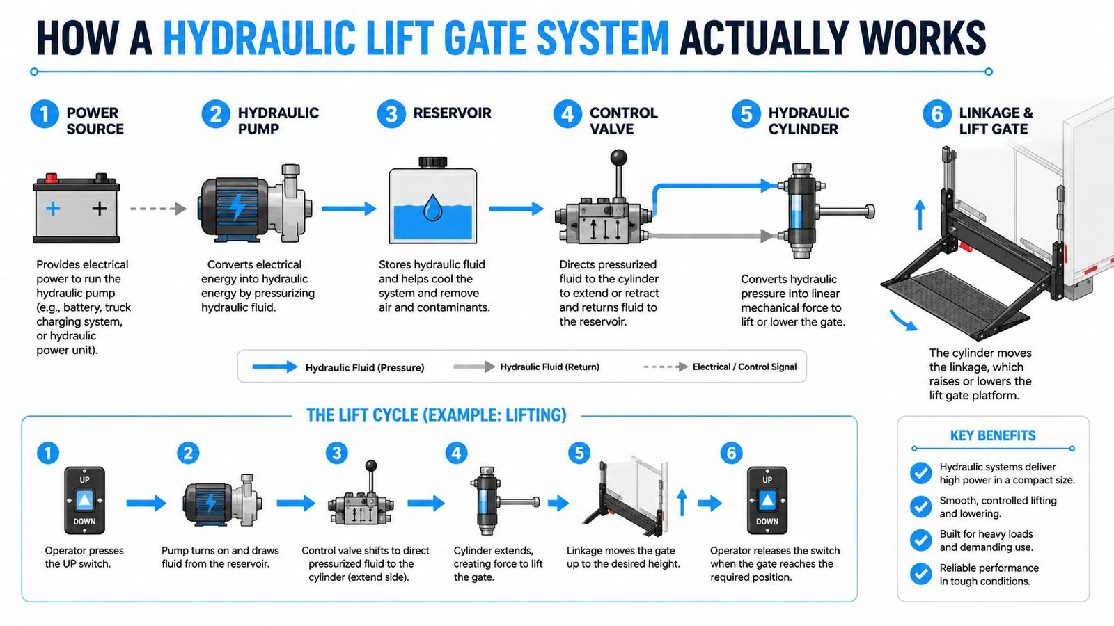
Start at the power source. Depending on the vehicle and gate design, electrical energy may come from the truck battery and charging system, while some installations use a dedicated hydraulic power unit. The battery circuit feeds the motor, solenoid, switches, relays, grounds, and control pendant or cab switch. If voltage drops too far during a start attempt, the hydraulic components may be healthy but unable to operate.
The motor drives the hydraulic pump, which draws fluid from the reservoir and sends pressurized flow toward the control valve. The reservoir stores the working fluid and allows air and debris to separate from the circuit. Use only the fluid specified by the liftgate manufacturer. In cold-climate service, technicians commonly encounter ISO 32 or AW-32 applications, but the equipment documentation should control the selection. Filtration and clean fluid protect valves, pump surfaces, and cylinder seals.
From the control valve, flow enters the actuator circuit. A directional valve determines whether the cylinder extends or retracts, while a flow-control arrangement can regulate movement. A single-acting cylinder may raise the platform through hydraulic pressure and allow gravity to lower it. A double-acting cylinder uses hydraulic pressure in both directions. Folding and rail-style gates often rely on a gravity-down function, so a smooth descent doesn't necessarily mean the hydraulic circuit is applying power in reverse.
The safety circuit is part of the operating system
Travel limit switches, operator-presence controls, platform locks, overload valves, interlocks, and emergency controls prevent unsafe operation. A wired pendant or cab switch sends the command, but the gate may refuse to move if an interlock is open or a limit switch is misaligned.
The same basic diagnostic logic applies to related hydraulic lifting equipment. For background on pump assemblies and their role in vertical transportation, see this overview of a hydraulic elevator pump. The component map is simple: power creates motor rotation, the pump creates flow, the valve directs flow, the cylinder creates force, and the linkage transfers that force to the platform.
Most Common Failure Modes and Warning Signs
The first question should be, “Does the motor receive and use power?” Not, “How much fluid should we add?” A gate that clicks without turning may have a weak battery, corroded terminals, a failed motor solenoid, a broken trailer plug pin, or a poor ground between the body and chassis. Chafed wiring at hinge points can create intermittent operation, where the gate works during one cycle and dies during the next.
Electrical symptoms often change with vibration and position. If the control works with the platform in one position but not another, inspect moving harnesses and connectors before blaming the cylinder. A solenoid that feels hot may have a high-resistance connection, excessive duty, or a control problem. Heat alone doesn't prove that the switch is defective.
Hydraulic symptoms become more persuasive after the electrical path passes inspection. Slow lifting, erratic travel, whining noise, or an inability to hold a load can point to low fluid, air ingestion, leaking hoses or seals, a faulty check valve, or contaminated fluid. Dark or milky fluid signals contamination or water intrusion. A check valve that allows bypass can make the platform lose lifting capacity, while air in the circuit requires bleeding.
Match the observation to the likely system
| Failure Mode | Visible / Audible Symptoms |
|---|---|
| Weak battery or corroded connection | Clicking, sluggish motor response, intermittent operation |
| Failed switch, relay, or solenoid | No command, single-cycle operation, motor fails to engage |
| Chafed wiring or poor ground | Fault changes with vibration, platform position, or weather |
| Low or contaminated hydraulic fluid | Slow movement, whining pump, erratic travel |
| Hose, fitting, or cylinder seal leak | Wet spots, falling fluid level, inability to hold a load |
| Faulty check or control valve | Bypass, drift, weak lifting capacity, inconsistent movement |
| Air in the hydraulic circuit | Jerky motion, spongy response, uneven travel |
| Worn pivot, bushing, or roller | Grinding, binding, skewed platform movement |
| Bent platform or damaged hinge pin | Misalignment, abnormal loading, latch difficulty |
| Failed latch or safety interlock | Gate won't secure, controls remain disabled, unsafe movement |
A platform that slowly drifts down under load deserves careful separation of causes. Internal cylinder seal bypass, a leaking valve, and an external hose leak don't produce the same pressure behavior, so visual inspection alone isn't enough. Hydraulic pressure testing provides the evidence that prevents a pump, cylinder, or valve from being replaced on assumption.
Mechanical faults can also overload a healthy hydraulic system. Worn bushings, seized rollers, bent arms, or cracked hinge pins increase resistance and make the motor sound weak. If the gate binds at a particular point in its travel, inspect alignment and linkage before ordering a pump.
A Safe Diagnostic Workflow That Finds the Real Problem
The order below keeps technicians from mistaking a power problem for a hydraulic failure. It also creates a record that a contractor can use if the repair moves beyond in-house capability.
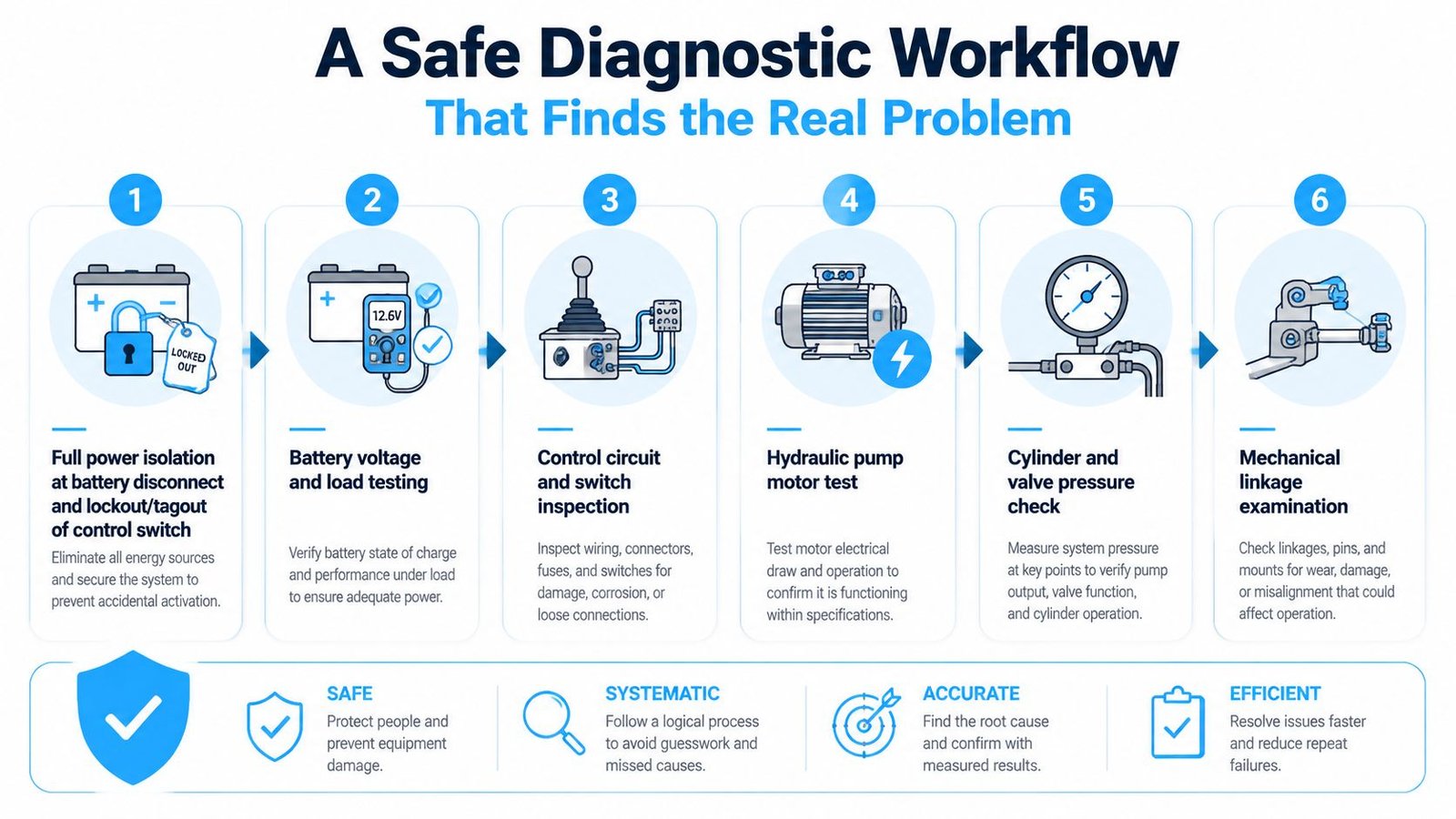
Isolate the unit. Park and stabilize the vehicle, clear the work area, disconnect the battery or use the approved battery disconnect, and lock out the control switch. Don't reach beneath a raised platform supported only by hydraulic pressure.
Verify battery condition and delivery. Check battery voltage at rest and during an attempted start, then inspect terminals, cables, fuses, breakers, grounds, and connectors. A voltage reading that collapses under demand can make a good pump motor appear defective.
Test the command circuit. Operate the pendant or cab switch only from a safe position. Confirm that the control input reaches the relay or solenoid, and test deadman, operator-presence, travel-limit, and other interlock functions without bypassing them.
Check the solenoid and motor path. Inspect coil connections and measure resistance according to the manufacturer's service information. Confirm that the solenoid receives the correct command and that the motor turns. A hot solenoid isn't automatically a bad switch, and a clicking motor isn't automatically a failed pump.
Inspect fluid and hydraulic components. Confirm reservoir level and fluid type, then look for dark or milky fluid, foaming, wet hoses, loose fittings, scored cylinder rods, damaged seals, and evidence of air ingestion. If the circuit contains air, bleed it using the approved procedure. Never treat a low level as the root cause until the leak is found.
Test pressure and holding behavior. Use the correct hydraulic pressure gauge and test point. Compare readings with the manufacturer's specifications, then observe whether the cylinder drifts under load, drops smoothly, or moves erratically. Pressure testing matters because visual checks can't reliably separate hose leakage, valve bypass, weak pump output, and load-related resistance.
Field observation: Troubleshooting without a gauge leaves the technician working blind. A pump may run while producing inadequate output, or a valve may bypass pressure even though the reservoir looks full.
After the fault is corrected, re-zero or reset the system according to its service instructions. Cycle the gate without a load first, then perform controlled load cycling appropriate to the equipment and site procedure. Post-repair cycling is important because worn seals, valves, and electrical connections can fail only after repeated actuation.
The following video can help maintenance personnel visualize the diagnostic sequence, but it doesn't replace the manufacturer's manual, site lockout procedure, or qualified service support.
Repairs You Can Do Versus When to Call a Pro
The dividing line is risk, not confidence. Trained maintenance staff can often handle external electrical and adjustment work when the equipment is isolated and the service information is available. That may include replacing a toggle switch, cleaning a ground connection, changing a damaged battery cable, resetting a breaker, adding approved fluid after the leak has been addressed, or adjusting accessible roller and latch hardware.
| Repair Task | Who Handles It | Reason |
|---|---|---|
| Replace switch or battery cable | Trained in-house staff | External component work with manageable electrical risk when isolated |
| Clean ground and terminal connections | Trained in-house staff | Corrects common power-delivery faults without opening the hydraulic circuit |
| Add approved hydraulic fluid after leak isolation | Trained in-house staff | Suitable only when fluid type and source of loss are known |
| Replace cylinder seals or packing | Qualified lift contractor | Requires hydraulic disassembly, contamination control, and pressure validation |
| Rebuild pump and motor | Qualified hydraulic or lift contractor | Requires component testing, correct assembly, and output verification |
| Set a relief valve or replace a load-holding valve | Qualified lift contractor | Incorrect adjustment can create uncontrolled movement or overload risk |
| Weld or straighten structural components | Qualified lift contractor | Affects rated capacity, alignment, and structural integrity |
| Perform rated-load testing or certification | Authorized qualified provider | Requires approved procedures, documentation, and applicable jurisdictional compliance |
Do not bypass a deadman switch, limit switch, interlock, overload valve, or platform lock to “get through the shift.” That workaround removes the information and protection the system uses to prevent unsafe movement. If personnel lifting or rated loads are involved, consult the applicable jurisdiction, licensing requirements, and standards such as ASME A17.1 where applicable.
Warranty terms, insurance requirements, OSHA records, and inspection documentation may depend on qualified sign-off. Crane Elevator Company handles related lift equipment work, including hydraulic packing and jack replacement, as described in its elevator pump motor repair services. Use the same discipline for a truck lift gate: keep in-house work within documented competence and send pressure, structural, and safety-critical work to the appropriate contractor.
Preventive Maintenance That Prevents Breakdowns
Reactive repair treats each failure as a surprise. A recurring program treats the lift gate as an asset with predictable electrical, hydraulic, and mechanical wear. For duty-cycled liftgates, quarterly servicing is a practical baseline, with more frequent inspections for equipment used every day, as outlined earlier.
Build the inspection around failure patterns
A useful quarterly visit should include:
- Electrical checks: Load-test the battery, clean terminals, inspect cables and hinge-point wiring, verify grounds, cycle solenoids, and confirm switches and interlocks.
- Fluid checks: Sample hydraulic fluid for moisture and particulates, verify the level and specified fluid type, and investigate unexplained loss.
- Cylinder and hose checks: Look for rod scoring, pitting, wet seals, chafed hoses, loose fittings, and abrasion.
- Mechanical checks: Lubricate approved pivot and bearing points, inspect bushings and rollers, examine chains and linkages, and test platform latches.
- Functional checks: Operate the gate through its travel, listen for whining or grinding, observe alignment, and validate holding behavior under an appropriate controlled load.
Record every result in the asset file, including the date, technician, observed condition, corrective action, and parts installed. Trends can expose a deteriorating ground connection, recurring fluid loss, increasing drift, or repeated latch adjustment before the gate strands a delivery.
Preventive maintenance cannot eliminate every failure. It can reduce guesswork and move repair decisions earlier, when an external cable, fitting, or adjustment may be simpler than a failed cylinder or damaged platform. Keep pressure, structural, and safety-critical findings within the scope of a qualified contractor.
For a broader maintenance program covering lifting equipment and related systems, review elevator preventative maintenance services.
Making the Right Call for Your Building
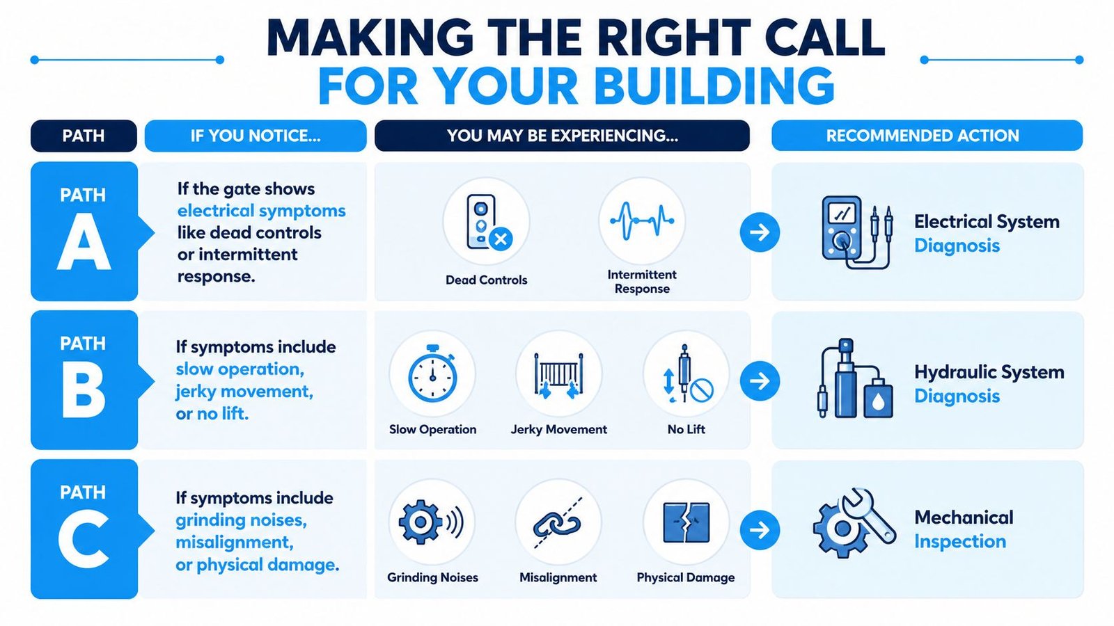
Use the symptom to choose the first diagnostic lane, but don't skip the safety check.
- Path A, electrical symptoms: If controls are dead, the motor only clicks, or operation is intermittent, begin with battery voltage under demand, fuses, cables, solenoids, switches, and ground connections. Don't open the hydraulic circuit until power delivery is verified.
- Path B, hydraulic symptoms: If the motor runs but the gate is slow, jerky, unable to hold a load, or visibly leaking, isolate the platform and arrange hydraulic diagnosis. Fluid condition, air, seals, valves, and pressure need to be evaluated together.
- Path C, mechanical or structural symptoms: If you hear grinding, see misalignment, find bent arms or cracked hinges, or identify a failed safety device, lock out the gate and call a qualified lift contractor immediately.
A lift gate isn't a garage door. It supports and moves loads, so cylinder repairs, warranty work, safety-circuit changes, structural repairs, and rated testing require qualified personnel. For the immediate next move, follow the diagnostic workflow, document the findings, then put the equipment on a recurring maintenance schedule.
Crane Elevator Company provides qualified lift repair support, including inspection of gates, barriers, interlocks, hydraulic fluid, hoses, fittings, seals, pumps, and cylinders. Visit Crane Elevator Company to request service or a second opinion for hydraulic lift equipment in Michigan and Ohio.