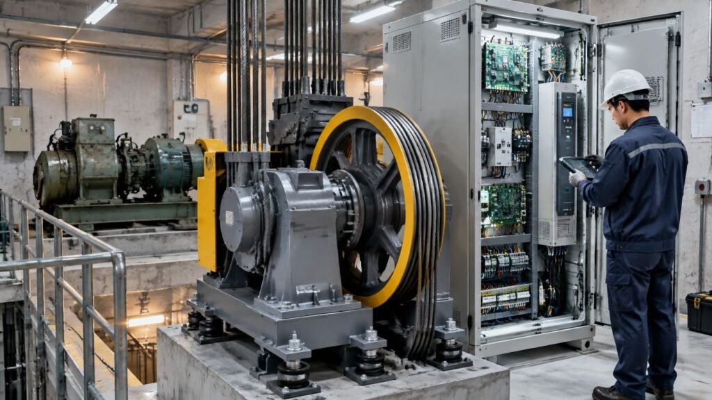
Your elevator starts with a thump, occasionally stops out of level, and has shut down again after a reset. The repair proposal mentions the motor, but the fault report mentions the drive. Before approving a replacement, you need to know whether those descriptions point to the same problem.
Elevator motor control is the link between electrical power and controlled movement. Understanding that link helps you ask a better maintenance question: what failed first, and what evidence supports the proposed repair?
Elevator Motor Control Types Compared at a Glance
Say you manage an older building with a noisy elevator start. Identifying the control system is more useful than guessing from the sound. The control type tells you how the equipment starts, regulates speed, and coordinates stopping, while its age and support status affect repair options.
Elevator motor control types and what they mean in practice
| Control type | How it controls the motor | Starting current | Speed control | Typical use |
|---|---|---|---|---|
| Ward Leonard DC drive | Adjusts generator output voltage supplied to the motor | Set by generator excitation and starting sequence | Smooth, fine regulation | Legacy traction |
| Fixed-speed AC with contactor starter | Applies full line voltage at start | High, abrupt | Single operating speed | Older low-rise and hydraulic installations |
| Two-speed AC | Switches between fast and slow motor windings | Current transients during starting and switching | Two fixed speeds | Older low-rise traction |
| VVVF AC traction drive | Adjusts voltage and frequency electronically | Electronically limited during acceleration | Smooth, profile-based | Traction modernization |
| Regenerative VVVF | Adds energy recovery to variable-speed control | Electronically managed | Smooth, with controlled electrical braking | High-traffic traction |
| Hydraulic soft starter with valve control | Ramps the pump motor supply and meters oil through valves | Reduced compared with direct starting | Car motion regulated through hydraulic flow | Hydraulic elevators |
Identify the family before comparing replacements
A motor-generator set supplying a DC traction motor points toward Ward Leonard control. Prominent contactors and a motor without an inverter may indicate an older AC arrangement. An inverter cabinet labeled VVVF or VFD points toward electronic variable-speed control, although a technician should confirm the actual configuration.
Hydraulic elevators belong to a different family. The motor runs a pump, while valves regulate oil flow and car movement. A soft starter controls electrical starting stress; it doesn't replace the hydraulic valve's motion-control function.
For traction machines, distinguish gearless from geared construction. A gearless motor drives the sheave directly; a geared machine has a reduction gearbox between them, changing the motor speed and torque required for travel.
- Record the labels: Have your maintenance provider document the controller nameplate, motor label, and panel identification without opening energized equipment yourself.
- Check the modernization history: A newer cabinet can operate retained machinery, so installation age alone won't identify the complete system.
- Separate motor from control: Use this guide to the motor for an elevator to clarify which equipment a proposal includes.
How VVVF Drives Replaced Older Motor Control
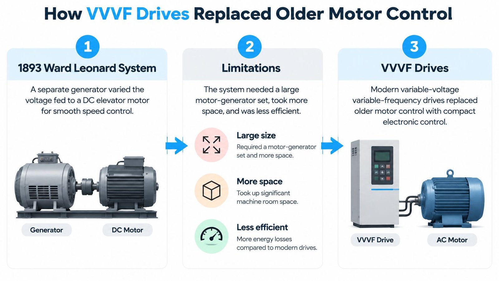
Early smooth elevator control required substantial rotating electrical equipment. The review of vertical-transportation drive development traces the Ward Leonard system to 1893, describes the arrival of AC VVVF technology roughly a century later, and identifies its widespread adoption over the last 30 years.
In a Ward Leonard installation, a separate generator supplied adjustable voltage to a DC elevator motor. Rather than abruptly connecting the motor to a fixed supply, the equipment could increase and decrease the voltage to regulate movement. The tradeoff was a large motor-generator installation with additional rotating equipment to maintain.
The change was from mechanically generated adjustable power to electronically controlled power.
What the cabinet components do
Think of a VVVF drive as a dimmer and cruise control working together. The analogy isn't electrically exact, but it captures the purpose: adjust the power supplied to the motor while continually regulating its movement against a target.
Variable-voltage variable-frequency control adjusts both quantities together to produce the required speed and torque. The drive doesn't just turn the motor on more gently. It regulates operation throughout the trip.
The main components have distinct jobs:
- Controller: Processes calls, operating permissions, and the intended motion profile.
- Rectifier and DC bus: Convert incoming AC to a DC supply and provide the drive's intermediate electrical stage.
- Inverter: Switches that DC supply into controlled motor power.
- Motor and encoder: Produce movement and provide speed or position feedback, according to the installation.
- Brake control and contactors: Coordinate mechanical holding and electrical switching within the approved system.
Follow a normal trip
A passenger registers a call. Once the doors, interlocks, and other required conditions permit travel, the controller prepares the motion command and the drive establishes the necessary motor torque. Brake release must be coordinated with that torque, rather than allowing the car to move before the motor can support the load.
The inverter then follows the acceleration command while feedback confirms actual movement. Approaching the destination, the controller reduces speed, completes positioning, and coordinates brake application.
Practical rule: A modern drive is part of an integrated elevator system, not a stand-alone replacement for the controller, brake, or safety functions.
This distinction matters when reviewing a modernization proposal. Electronic control changes starting demand, heat production, power quality, and component loading. It also has to work correctly with retained machinery, inspection operation, door equipment, and safety circuits.
How Motion Profiles Set Ride Quality and Leveling
Passengers feel how acceleration changes, not just how fast the car travels. An elevator can reach its intended speed and still feel uncomfortable if the transition into acceleration is abrupt.
The drive follows a programmed speed reference. A simple reference with sharp corners asks the motor to change its behavior suddenly. An S-curve profile rounds those transitions, limiting jerk, the rate at which acceleration changes.
A review of electric elevator drive systems reports an estimated 88% reduction in jerk for an S-curve-controlled prototype compared with operation without the drive. That's a prototype result, not a guaranteed improvement for every modernization.
Smooth travel and accurate stopping require coordinated control
Consider carrying an open cup of coffee. Gradually increasing your walking pace is easier to manage than suddenly lunging forward, even if your eventual speed is identical. Elevator motion follows the same practical principle.
Near a landing, the controller must coordinate deceleration, final low-speed positioning, and brake application. The brake isn't supposed to compensate for an inaccurate approach by catching a car that's still moving too quickly. Accurate leveling depends on the relationship between the commanded motion and the actual response.
That relationship involves feedback loops. The speed loop compares intended speed with measured speed; the current loop regulates the electrical effort needed to produce torque. Poor tuning can cause vibration, leveling errors, nuisance trips, or rollback even when motor horsepower is adequate.
What commissioning should demonstrate
A useful acceptance record should show more than a successful demonstration ride.
- Loaded and empty-car runs: Verify behavior under different balancing conditions and in both travel directions.
- Stopping repeatability: Record whether the car consistently reaches the landing, rather than relying on a single satisfactory stop.
- Motor current: Check the electrical effort during acceleration, steady travel, and low-speed positioning.
- Encoder alignment and feedback: Confirm that the drive receives reliable information and that its motor setup is correct.
- Brake timing: Verify coordination during departure and arrival, including resistance to rollback.
- Speed transitions: Check changes between inspection, leveling, and normal contract speed.
Specify the complete motion profile, not just the motor horsepower.
Retaining the existing ropes, sheave, traction machine, or brake doesn't eliminate commissioning work. Those components establish mechanical inertia and friction that the new controller must accommodate. A replacement cabinet must be tuned to the installed machine, not merely loaded with a convenient default configuration.
Starting Current and Power Demand in Modern Drives
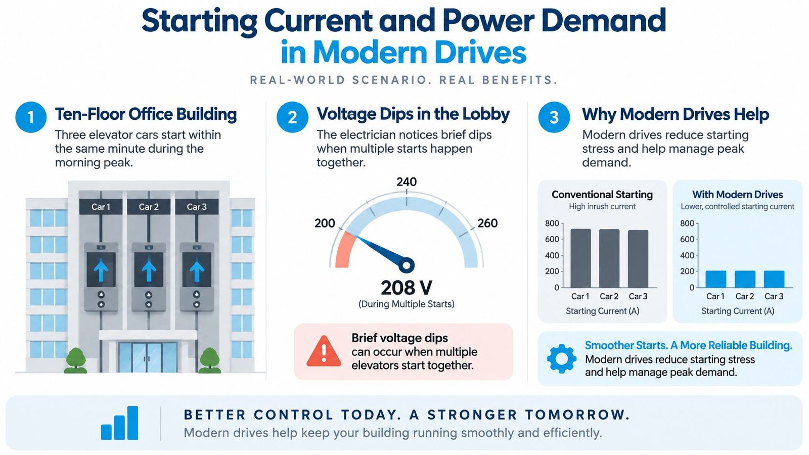
Consider a hypothetical office building where several cars start close together during the morning rush. An electrician notices brief voltage dips affecting lobby equipment. The important question is whether those dips coincide with elevator starts, another building load, or a supply problem.
Starting current is the current drawn while a motor begins moving and accelerates its load. Conventional direct starting can impose a sudden electrical demand. Electronic variable-speed control manages the acceleration instead of applying the same abrupt starting condition.
The difference between an isolated motor start and overlapping building demand is worth visualizing.
Separate current reduction from energy savings
The elevator motor-control study indexed by EconPapers discusses Hong Kong Electrical and Mechanical Services Department guidance reporting up to 80% lower peak starting current with variable-speed drives relative to conventional drives, alongside energy-efficiency findings of approximately 30% to 40% savings for applicable elevator classes using newer controls and related technologies.
Those measures aren't interchangeable. Peak current describes an electrical starting condition. Energy consumption describes electricity used over time. Reducing a short starting spike doesn't mean the entire elevator's electricity bill falls by the same proportion.
Demand charges require another distinction. Utilities may assess demand over a billing interval rather than an instantaneous motor-start peak. A lower starting current can help the electrical service without delivering an equivalent reduction in billed demand.
Measure the installation rather than promising a percentage
A meaningful assessment should connect electrical readings with operating conditions:
- Traffic and duty cycle: Frequent service creates a different savings opportunity from a mostly idle elevator.
- Car loading and counterweighting: The imbalance determines how much work the motor performs on a particular trip.
- Motor type and travel height: These influence acceleration, cruising, and stopping requirements.
- Regenerative equipment: Energy returned during favorable travel conditions changes net consumption.
Shaped starts and stops also reduce abrupt mechanical loading. That benefit belongs in a reliability assessment, but it shouldn't be converted into a maintenance-cost promise without supporting records.
Hospitals, offices, schools, and busy multifamily buildings are useful candidates for measurement because small differences per trip can accumulate through frequent operation. Request a representative operating baseline, then compare post-upgrade performance under similar traffic conditions. Otherwise, a change in occupancy can look like a drive improvement.
Diagnosing Motor Controller Faults Before Replacing Parts
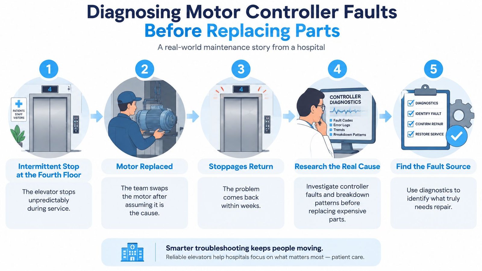
Consider a hypothetical hospital elevator that intermittently stops at the same landing. The team assumes the motor is responsible and replaces it, but the shutdowns return. The replacement wasn't necessarily defective; the original diagnosis may have confused the component that stopped with the component that initiated the stop.
A Hong Kong University of Science and Technology thesis on elevator performance identifies controller faults, alongside car-door and landing-door faults, as major contributors to breakdowns and discusses controller failures as an indication of the wear-out phase in aging equipment.
That makes recurring faults a lifecycle-maintenance issue, not just an invitation to reset the drive again.
Use symptoms to choose tests, not replacement parts
The following causes are diagnostic possibilities. A symptom alone doesn't confirm any of them.
Motor control symptoms, likely causes and what to measure
| Symptom | Likely motor-control cause | What to measure |
|---|---|---|
| Intermittent shutdown with no clear pattern | Loose connection, failing controller board, or encoder problem | Fault history, encoder signal, connection condition |
| Rollback at start | Brake timing error or low-speed torque shortfall | Brake release timing, motor current at start |
| Leveling overshoot or undershoot | Speed-loop tuning or encoder misalignment | Leveling accuracy, stopping repeatability |
| Nuisance trips after heavy use | Drive overheating, cooling-fan failure, or capacitor deterioration | Drive temperature, starts per hour |
| Repeated faults after motor replacement | Controller or power supply may be the initiating failure | DC-bus behavior, braking-resistor activity |
| Vibration during travel | Tuning mismatch or worn mechanical parts | Motor-current ripple, acceleration and jerk measurements |
Follow the evidence in order
Preserve the fault history. Export the event log before clearing it. Sort events by time, direction, landing, and known loading conditions. Distinguish the earliest recorded fault from shutdown messages generated afterward.
Record current and DC-bus behavior during controlled runs. Qualified technicians should correlate the drive's diagnostic trace with supply measurements. A bus-voltage disturbance that precedes the trip deserves different treatment from one produced during the stop.
Check temperature and braking activity. Review drive and motor temperature, cooling airflow, fan operation, and braking-resistor behavior. Inspect connections under the appropriate isolation procedure, not by reaching into an energized cabinet.
Compare performance with workload. Trend leveling accuracy and nuisance trips against starts per hour. A fault appearing only after intensive service suggests a different test plan from one occurring on the first trip after a long idle period.
Determine whether the fault follows the component or remains with the system. Compare evidence before and after previous repairs. If the same event persists after a motor replacement, investigate the controller, feedback, brake coordination, wiring, and supply instead of automatically ordering another motor.
A temporary disturbance becomes a defensible diagnosis when measurements identify the event and subsequent monitoring supports that conclusion. A reset followed by normal operation isn't enough. Recurrent temperature, feedback, insulation, or bus-related abnormalities require a corrective plan.
For hydraulic equipment, an elevator pump motor repair assessment should also distinguish electrical starting faults from hydraulic loading or valve problems.
Before ordering parts: Identify the initiating failure and explain how the proposed repair removes it.
Electrical investigation requires qualified personnel, suitable test equipment, and code-compliant disconnecting means. Owners can preserve reports and operating observations; they shouldn't open cabinets, probe circuits, or repeatedly reset an elevator with unresolved shutdowns.
When Regeneration Pays Off and When It Does Not
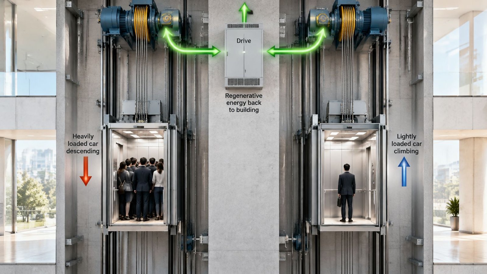
A traction elevator's motor doesn't always consume power to move the car. A heavily loaded car descending, or a lightly loaded car ascending, can drive the motor as a generator because of the car-counterweight imbalance.
A regenerative VVVF drive returns that generated energy to the building's electrical system instead of dissipating it through braking resistors. The energy flow is easiest to understand as a connection between the machine, drive, and building supply.
Compare operating opportunities and project requirements
The published text of ANSI/ASHRAE/ICC/USGBC/IES Standard 189.1-2023 Addendum ac specifies regenerative variable-speed drives for qualifying traction elevators in new buildings and, for traction elevators with a rise of at least 75 ft (23 m), a motor with at least IEC Class IE2 efficiency and a power-conversion system capable of recovering potential energy. Whether those provisions govern a particular project requires confirmation of the adopted requirements and their scope; they aren't a blanket retrofit instruction.
Energy options for elevator motor control and when each fits
| Option | Best fit | Energy effect | Main condition |
|---|---|---|---|
| Regenerative VVVF drive | High-rise, high-traffic buildings | Returns available braking energy to the building | Electrical system must accommodate returned power |
| Non-regenerative high-efficiency VVVF drive | Moderate-traffic buildings | Improves motor-control efficiency without returning braking energy | Compare lifecycle cost using actual traffic |
| Standby mode and improved dispatching | Buildings with long idle periods or inefficient trip allocation | Reduces idle consumption or unnecessary operation | Preserve required service and tenant access |
| Cab lighting and ventilation shutoff when unoccupied | Buildings with compatible cab controls | Reduces auxiliary electricity use | Maintain required lighting, ventilation, and emergency functions |
Before specifying regeneration, answer these questions:
- Is traffic sufficient? Frequent favorable travel creates more recovery opportunities than occasional short trips.
- Can the electrical system accommodate the output? Confirm compatibility, power quality, and how recovered electricity will be used.
- Would another measure provide better value? Compare regeneration with a simpler drive, idle controls, and dispatch improvements rather than treating it as the default.
The following video provides another visual reference for regenerative elevator operation.
Build the retrofit worksheet around annual trips, average load, motor type, measured peak demand, utility rates, available electrical capacity, and maintenance impact. Request motoring demand, recovered-energy estimates, input power factor, harmonic performance, thermal requirements, and emergency-rescue compatibility. Rated horsepower alone won't answer those questions.
Decide Between Drive Repair and Modernization
Regeneration can be attractive without being the best next investment. The IndexBox analysis of regenerative-drive applications emphasizes the importance of operating conditions and reports recovery of roughly 30% to 70% of energy otherwise dissipated as heat in modern traction elevators. That isn't the same as reducing total elevator electricity use by that amount.
The repair decision should combine a demonstrated failure mechanism with the equipment's remaining supportability.
Build a defensible scope
Collect a representative operating record. Assemble fault history, trip counts, starts per hour, callbacks, and previous repairs. Include busy and quiet periods rather than selecting only the worst day.
Confirm parts and diagnostic access. Determine whether boards, drives, encoders, documentation, software tools, and technical support remain available. A repairable fault can still expose an obsolete system's support limitations.
Require loaded-run evidence. Use motor current, DC-bus behavior, temperature, and feedback records to support the proposed scope. Record what was tested and what remains uncertain.
Compare complete lifecycle costs. Include repair cost, expected downtime, commissioning, electrical work, maintenance implications, and realistically modeled energy savings. Keep accessibility and service continuity separate from simple energy payback.
Confirm installation requirements. Resolve electrical capacity, disconnecting means, permits, inspections, and compatibility with retained equipment before authorizing the work.
Preserve future service choices
Non-proprietary controls allow service by any qualified service provider, rather than restricting future maintenance to a single vendor. All our modernizations use non-proprietary control systems. When reviewing an elevator modernization scope, include documentation and service access in the comparison, not just cabinet hardware.
For each option, use the same calculation template: annual trips and average load establish duty; motor type and measured demand establish the electrical baseline; utility rates convert modeled consumption into cost. Then account for available electrical capacity, installation expense, and maintenance impact. Divide net project cost by credible annual net savings only where those savings can be supported.
We offer a second opinion on an existing or ongoing elevator problem at no extra charge, including a visit and a solution plan. For service or questions, call 1-734-726-4247. Bring the fault history, previous repair reports, and measurements so the quote reflects the measured failure rather than a guess.
If recurring shutdowns have left you deciding between another repair and a control upgrade, visit Crane Elevator Company to discuss a diagnostic review and second opinion. We can help you evaluate maintenance, repair, and non-proprietary modernization options around the elevator's actual condition and your building's operating needs.